DIY
Printed Circuit Board Manufacturing (Nov. 2012)
Every printed circuit board
that ever went into a Frantone product after 1999 was hand made by myself.
That is a lot of circuit boards! There are so many tutorials about
how to make "do it yourself" PCB's, and any of them might be fine for prototyping
a simple design or one off board, but imagine how hard it would be to mass
manufacture dozens of different PCB designs to the tightest possible tolerances
for an entire product line for a decade, all by hand? Well, so far
as I am aware, I am the only one in the boutique effects world crazy enough
to have tried it - and really done it. And this is how....
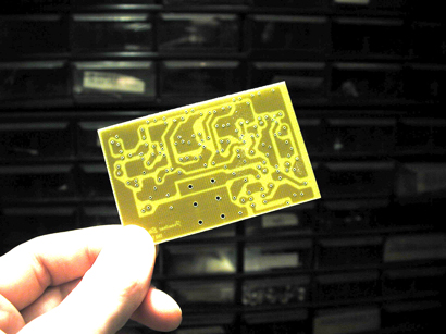
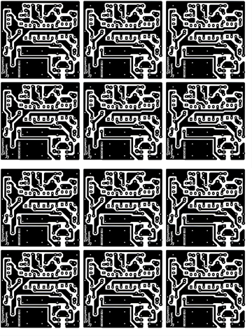
Photo positive artwork for exposing Brooklyn PCB's.
I always prototyped my designs
on a regular perf breadboard, and rendered the schematics and circuit layout
in Protel. Circuit Auto-Routing? I think not. All of
my circuit board layouts and trace routing was done manually, using templates
I made in Protel to establish the proper spacing and tolerances for the
pads, traces, and lead spacing. But to extract the design from Protel
meant that I had to print out the PCB file to paper, and to make my optical
plates to expose sets of PCB's meant that I had to scan the rendered paper
artwork at 4x scale, then arrange multiples of the artwork with proper
scaling corrections in a photo program to render photographic plates that
I would use to UV expose positive resist 4X6 inch bare copper FR4 boards.
In the later years as technology improved I switched to a thermal transfer
process to transfer resist to the bare copper in a converted heat press.
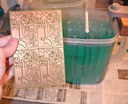
Bubble, bubble, toil and trouble... Etching!
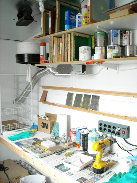
My ventilated work room, 2008
For etching I used a special
ventilated workstation that I also used as my silk screening table.
There I would set up my etching tank that contained an air bubbler system
that I made with an aquarium pump and a submerged aquarium heater that
would circulate and heat a solution of sodium persulphate to 120°f.
Ventilation and a chemical respirator are necessary to work with this stuff
because of the outgassing of sulfuric acid during the etching process,
which is quite harmful to breathe. I could etch up to five 4X6" FR4
plates at one time, and 10-20 plates would make a typical manufacturing
run, yielding between 40-100 individual effect PCB's.
But these etched boards
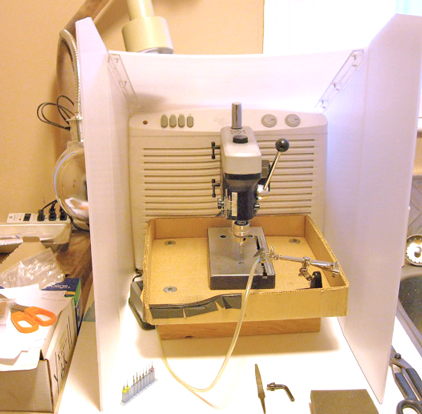
needed to be drilled, and here is where it gets difficult. For starters
I bought a jewelers drill press, which out of the box was intended to be
for this kind of work, but it proved very inadequate. The press was
too sloppy and quickly overheated. I created a forced air cooling
system that used a CPU fan to pressurize the motor casing, and I drilled
vent holes above the motor to allow the hot air out. Then I had to
accurize the drill, because I was using 30mil high speed tungsten carbide
bits that were inherently prone to shatter if the center of rotation deviated
more than 4mils. To get this accuracy it was necessary to balance
the chuck with hand filing, then to center the chuck by fitting it to the
drill cone using flakes of aluminum foil as shimming material. With
some time and care I had accurized the press to within 2mil (.002") of
center deviation, and now it was ready. I constructed a HEPA filtered
vent hood housing for the press within which I could work, to create the
minimum amount of hazard. I still had to wear a respirator while
drilling, as the constant inhalation of FR4 dust is very bad for the inner
parts of the lungs, causing a form of silicosis with long term exposure,
or in the case of sudden high level exposure, can cause sudden death by
cardiopulmonary edema. Nasty stuff. But with safety measures
in place I also had to employ another aquarium pump that I used to blow
air to the drilling point with a plastic tube, which would be necessary
to clear the dust off of the drill dies so that I could see what I was
doing.
To drill the PCB's in volume
I invented a die system whereby every board had its own drill die that
I made by hand. The die consisted of a thick aluminum plate that
I machined down to a flat smooth surface, with registration pins that aligned
a stack of PCB's, and contained enlarged recessed holes for each drill
register into which the drill bit would plunge after going through the
bottom board of the PCB stack. Each individual circuit board was
cut out of the larger etched plates, and on every board I had selected
4 holes that would be used as registration points through which the registration
pins would go to center each board in the drill die. I had to line
up and hand drill each of the four registration holes on every board to
start a run. The boards could be stacked up to 7 high in each drill
die, and then on top of the stack was placed a brass drill guide plate
that contained the drill register for the PCB, and tightening nuts to hold-down
screws mounted in the base of the die created a firm aligned stack of boards
ready to be drilled. With a few bit changes a stack of boards could
be drilled pretty fast, even with upwards of 100-200 holes per board.
Depth control was necessary
to insure that when the bit plunged through the bottom of the stack into
the drill recess that it stopped short of hitting the bottom of the hole.
If the bit were to bottom out - like when I would forget to set it - the
bit would shatter, creating a big problem with carbide fragments embedded
in the boards.
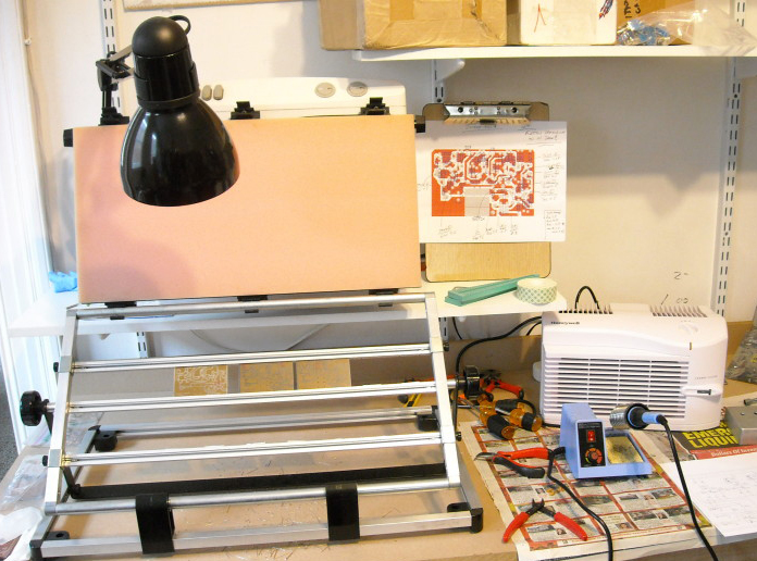
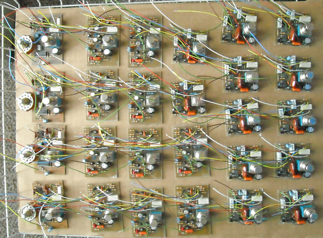
PCB assembly station, 2008.
After the PCB's were drilled
I stored them in plastic zip bags to prevent any patina from forming on
the copper. I also wore nitrile gloves whenever handling the bare
copper boards to keep my prints off as well. The next stop was the
filling station, where I had a board assembly flip-jig in which I could
place any number of boards to fill, flip over, and solder simultaneously.
A hold down pad on the top kept components in place while soldering.
When the boards were completely
filled and wired they went back to the vent room to get a bath in methyl
alcohol, which dissolved all of the resin flux. After drying a white
powdery film of resin would remain, which was taken off with a dry toothbrush.
Then the clean PCB's headed to the paint room where they were conformal
coated. This added an insulating layer which also prevented oxidation.
The PCB's were now completed and ready for installation.
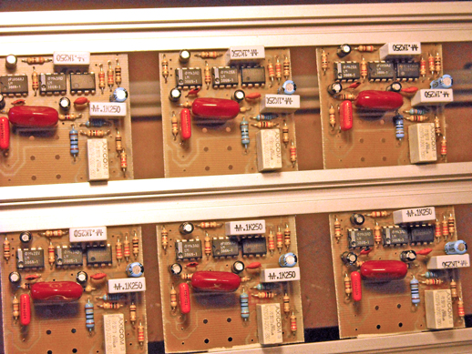
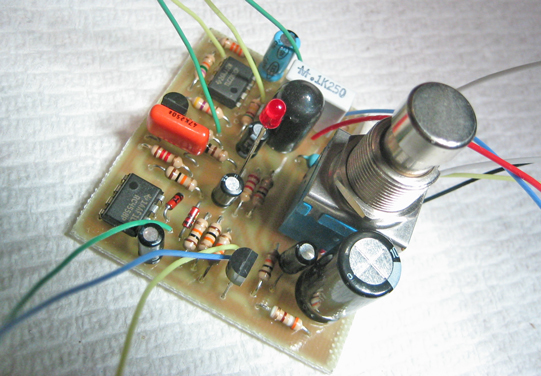
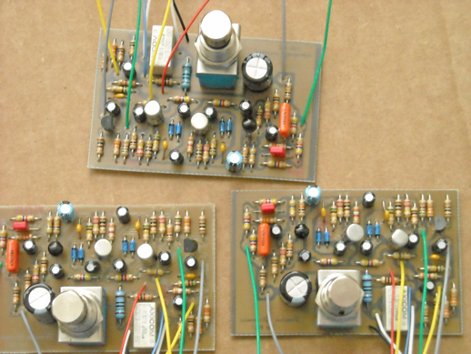
A run of completed mixed PCB boards.
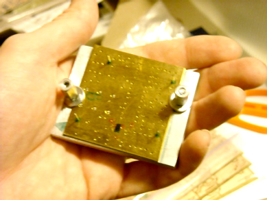
A completed Sandwich PCB. The black part behind the LED is my
proprietary precision optocoupler, also manufactured in house.
Completed Sweet PCB's.
So, why did I do it this
way when anyone can outsource PCB manufacturing and get great results?
Well, mostly because it was cheaper and I could make changes at any time
- which often happened when a component would change size, or a revision
of the circuit was required. It was also part of the philosophy of
complete vertical integration that I established for Frantone in 1999.
I machined, painted, and silk screened every case in house - and every
PCB was also designed, etched, drilled, and filled by hand.
I wanted every Frantone pedal to be exactly what it was said to be: Completely
Made By Hand, With Love. :)
Ask
Fran: Introduction to the Commodore 64 (C-64) Computer (Nov. 2012)
In this video I show some
of the basic starting skills you need to configure the look of your C-64,
how to access data on tape and floppy disc, maintenance for tape drives,
and some simple codes to get things going. Consider this C-64 for
newborns. No opcodes, stack, or registers in this so if you already
know what I am talking about this video will be pretty lame :).
Ask
Fran: Build Your Own Microscope! (Nov. 2012)
Fran's
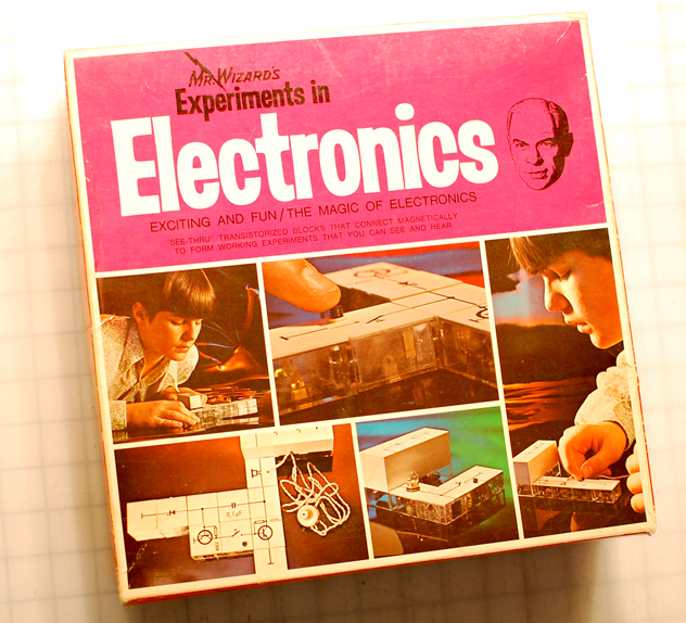
Favorite Toy In History: (Oct. 2012)
Mr. Wizard's
Experiments In Electronics c.1972
In 1977 I had a wish
list, and on top of that list was a box that was gathering dust on the
shelves of Allen's Variety Store that had my attention all summer.
It was far out of the price range of my measly 50¢ a week allowance,
but on Christmas of that year it ended up under the tree. This
toy was better than cool..... It was so awesome that it would actually
determine the course of much of my life. This toy made me into a
scientist!
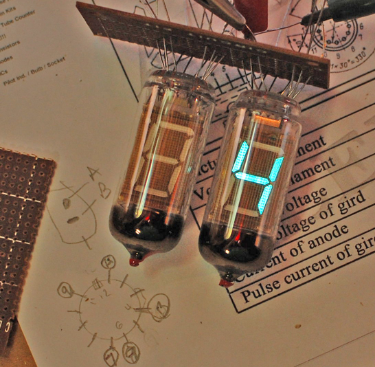
Another cool project in the
works is a converter for Soviet Vacuum Fluorescent Displays like this one
on my bench:
These larger USSR
made displays use a lower filament voltage (+1.5VDC) and higher grid voltage
(+25VDC) than most VFD's you would find, which makes using common 12V VFD
clock drivers impossible. I will have to make up an array of 30V
PNP transistors for a step up display driver stage. A lot of work,
but ain't they perdy??!
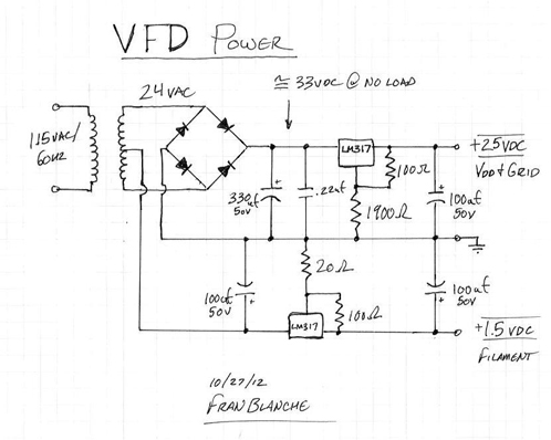
Here is a handy schematic
for my USSR-VFD power supply which you can customize for any VFD display
by changing the R1 and R2 values on each LM317 voltage regulator to get
the desired output you require for the filament and grid supplies.
I used a 115v/24v center tapped 2amp transformer, and keep in mind that
these tubes do draw some current so best to give a good 100ma of overhead
in the supply for each tube you want to drive. This supply has a
1.5v regulated filament supply, but if you are using multiple tubes you
can also stack the filaments in series to divide a higher combined supply
voltage (example: 5X 1.2v in series = 6v supply)
Nixie
Counter Project (Oct. 2012)
This is the start of a side
project I have been doing in my spare time, in my new and still coming
together science lab. I wanted to create a universal 4-bit controlled
nixie display driver that could be used as a module for any application.
Here I have breadboarded an automatic counting circuit with a clock, and
also a separate high voltage board for the nixie display that I have hooked
up to a manual rotary switch for demonstration. The ultimate goal
is to reduce this down to a single condensed board.
I leave out some details
in this brief video demonstration, but I will post the schematics and technical
data for the project when I get it all together.
Update: Phase 2!
Here I demonstrate the completed
breadboard, with power supplies and the interface for the logic to the
high voltage Nixie displays.
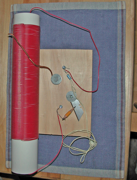
You
can make a radio!
This is a 'foxhole radio'
that I made years ago for an R. Lee Ermey challenge in 2003 to show that
in fact you can make a radio receiver from common stuff - that is, so long
as you have a crystal earset lying around. The razor should be blued
for greatest diode effect but they do not make blued razors anymore, so
I substituted a modern hardened steel blade. The graphite pencil
point acts as the anode and you move it around the the razor to find the
point of contact where the diode is detecting the best. You tune
the circuit by adjusting a wire which you tie to earth ground to contact
on the coil, where the insulation has been shaved away - presumably by
the razor before you put it in your now fully functional radio!
When I worked at an AM radio
station in my 20's the bathroom was almost right under the broadcast antenna
tower, so I made a modern tuned diode detector with a tiny speaker that
I hung on the wall in there, and it played the station out loud 24/7 with
no electricity. Just the power of the rectified radio waves - which
was at a strength of about 10 volts per cubic foot in the bathroom - and
a good earth ground on the cold water pipe was sufficient. There
is also the story of the oven in a trailer park that played country music
near another radio transmitter I worked at that was local legend..... and
true! Tuned resonance at work.
The
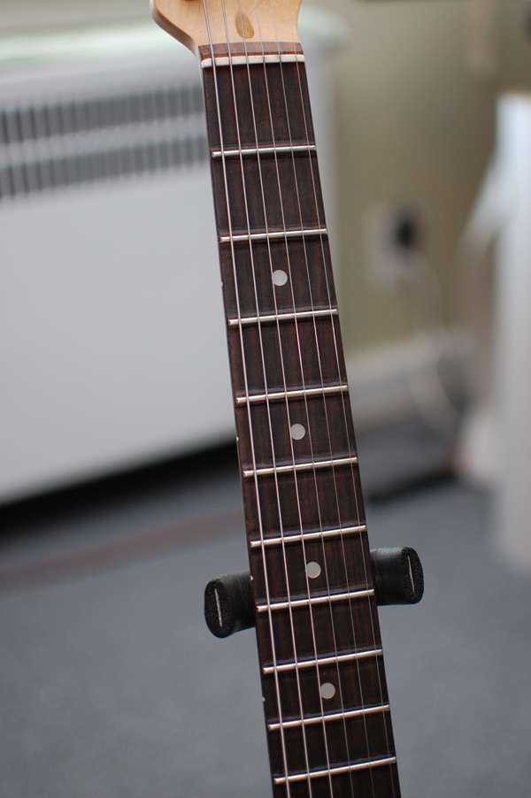
Frantone Fretboard (July 2012)
Despite being very busy
in the corset world I still strive for new innovations in guitar gear -
the latest being The Frantone Fretboard! I made this special recessed
flat contour fretboard with a new type of scalloping technique I developed
for one of my own guitars. This new fretboard has allowed me to play
guitar every day after a two year hiatus from playing due to arthritis.
Considering how much a difference this has made for myself I wonder what
it can do for other players who are not at all limited as I am.
Part one of making the Frantone
Fretboard. The audio is bad in this video due to the noise
canceling feature of my old webcam. But you can see what I am doing.
New
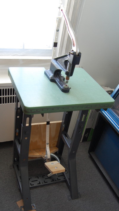
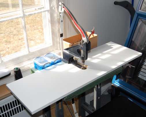
Grommet Press Project (Feb. 2011)
I recently completed my second
kick press project. I bought a used industrial sewing table which
I customized to mount my hand press to it, then constructed the foot pedal
with the necessary leverage to amplify the force of the hand press from
10:1 to 18:1. This new kick press delivers 650lbs of force to the
die with just 36lbs of pressure on the pedal, and all completely hands
free.
I made a removable
melamine work surface that is level with the lower die and the new grommet
press was done.
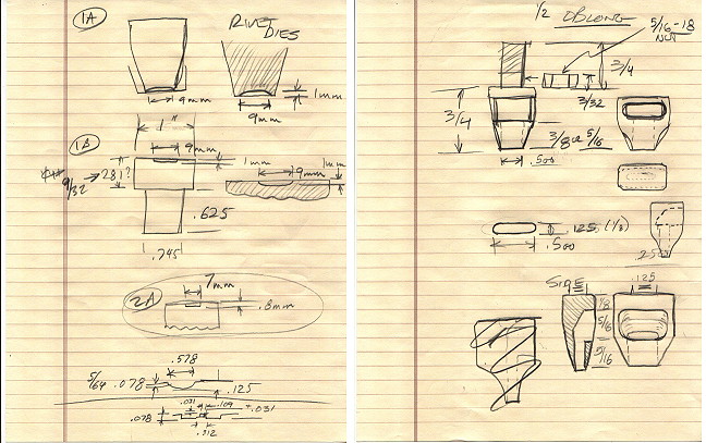
I then wanted to make this
kick press more than just a grommet press, so I designed a series of practical
die sets for other press operations that I do frequently. I contacted
my good friend Bud Mohrman at TAPE Inc.
to make the dies for me, and fortunately he is one of the last hard core
machinists that can cut dies directly from high strength tool steel.
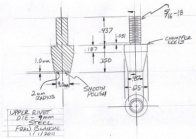
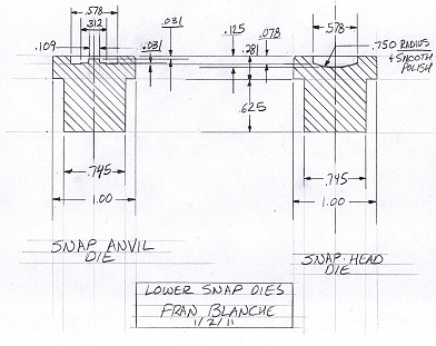
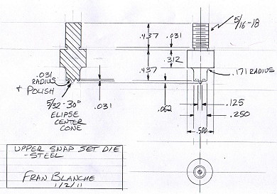
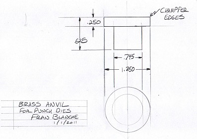
I made some initial sketches
from my mental images to better visualize the manufacturing tolerances
for these dies.....
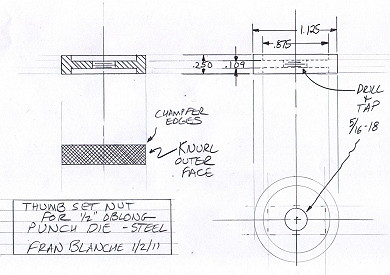
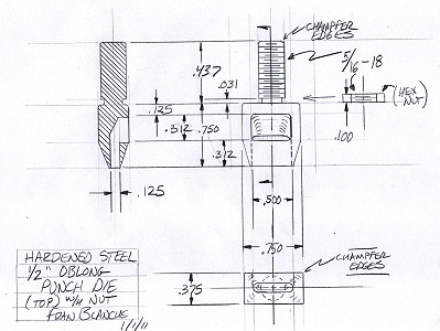
I then made a series of mechanical
drawings that contained my calculations for tolerance and proper contouring,
finish, and measurements for each die. Mechanical drafting is a specific
language which communicates the design concept in a way that another person
can manufacture the part to exact proportions and have the parts interact
with proper tolerances. The Machinist will not make judgment calls,
it is up to the designer to be very clear on all parameters. If the
designer makes a mistake or miscalculation then the part will either not
fit, or not function as needed. These drawings were made with a requested
manufacturing tolerance of ±.005 inches. No computers here,
I do everything in pencil on paper at my drafting table....
The results were very good,
and Bud did a magnificent job. There were a few small tweaks, and
the dies work great, as expected. Here are the actual dies....
The 9mm Rivet Die set.
The 3 piece Snap Die set.
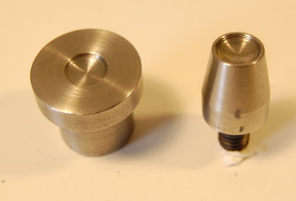
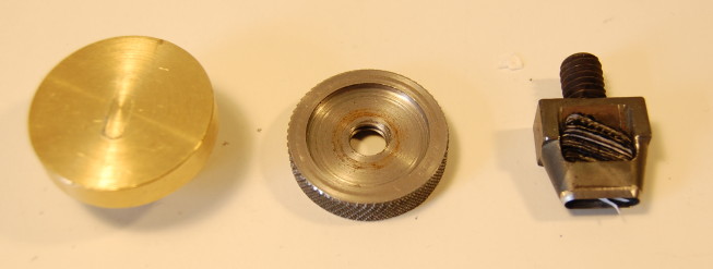
The 1/2" oblong punch die
and brass anvil, with the finger adjustable nut to set the punch angle.
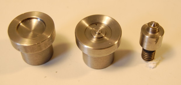
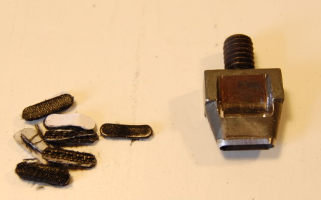
The oblong punch and ejectorate.
Here
I demonstrate the rotary punch and grommet kick press I made for creating
my heavy duty lacing systems. How heavy duty are they? Watch
and find out!